QUICK ANSWER
What to Know First
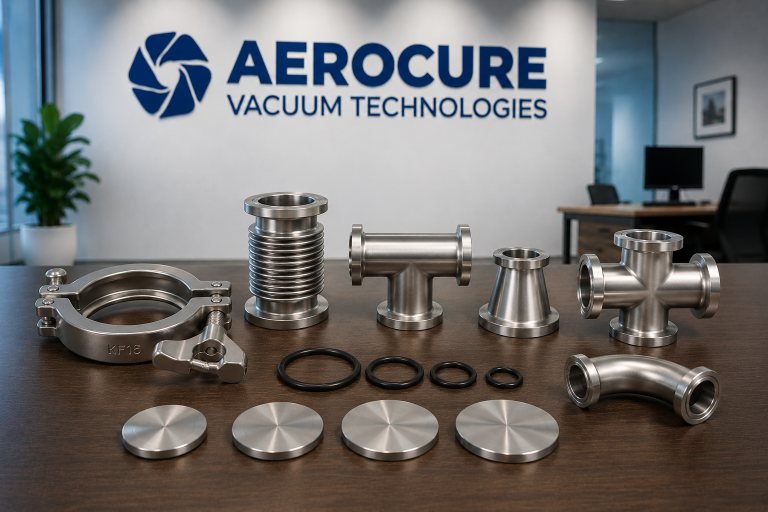
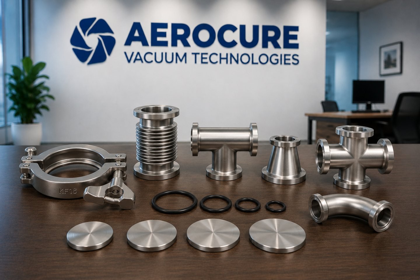
A common KF joint uses an elastomer seal on a centring ring and a peripheral clamp. Common ISO-K and ISO-F joints use a centred elastomer seal with clamps or bolts. Common CF joints use opposing knife edges and a metal gasket. Match the exact family, dimensions, materials and operating limits.
OVERVIEW
The Technical Context
Detachable vacuum joints connect gauges, valves, pumps, chambers and pipework. The connection must match mechanically and seal under the required conditions while allowing suitable access, support and maintenance.
The names alone do not establish a complete pressure, temperature or structural rating. Seal material, flange design, fasteners, neighbouring equipment and the manufacturer's instructions determine the acceptable assembly.
- Identify flange family before nominal size.
- Treat the seal and hardware as part of the joint.
- Protect sealing faces from dirt and damage.
- Use exact dimensions and equipment instructions.
ENGINEERING GUIDANCE
Compare the Common Connection Families
| Family | Typical seal | How it is secured | Selection focus |
|---|---|---|---|
| KF / ISO-KF | Elastomer O-ring held by a centring ring | Peripheral clamp | Flange/centring-ring size, clamp type, seal compatibility and access |
| ISO-K | Elastomer O-ring/centring assembly | Claw or collar clamping arrangement | Matching flanges, correct clamps, seal support and loads |
| ISO-F | Elastomer O-ring/centring assembly | Bolted flange arrangement | Bolt pattern, hardware, mating arrangement and support |
| CF | Soft-metal gasket compressed by knife edges | Bolts around the flange | Gasket material, knife-edge condition, hole pattern and approved assembly |
ENGINEERING GUIDANCE
Nominal Size Is Not Always the Outside Diameter
KF and ISO nomenclature commonly refers to a nominal bore. CF may be described by nominal bore in some markets or flange outside diameter in others. A single number without the family and unit can therefore identify different items.
Use a drawing, manufacturer part identification or clear photographs with dimensions. Record the outside diameter, bore, bolt-hole pattern where relevant, sealing face and mating component. Do not select an adapter from a guess based on appearance.
ENGINEERING GUIDANCE
Review Seals, Temperature and Process Compatibility
Elastomer seals support convenient assembly, but their permitted temperature, gas compatibility, permeation and outgassing characteristics depend on the material and duty. Common metal-gasket CF joints are used where lower outgassing and higher-temperature preparation are important.
That distinction is a selection starting point, not a universal rating. Special seals and hardware also exist. Confirm the exact gasket or O-ring, flange material, preparation and complete assembly against the supplier documentation.
ENGINEERING GUIDANCE
Prepare the Joint without Damaging the Seal
- Identify and inspect both mating sealing surfaces and the correct seal.
- Use the cleanliness and handling procedure required for the process.
- Protect O-rings from cuts, dirt, rolling or incompatible chemicals.
- Protect CF knife edges and gaskets from scratches or handling damage.
- Use the specified clamps, bolts and tightening procedure; don't substitute a generic torque.
- Follow the gasket supplier's replacement/reuse instructions.
ENGINEERING GUIDANCE
Plan Adapters, Bellows and Mechanical Support
An adapter can change connection family or size, but it also adds joints, length and possible conductance restrictions. Bellows can accommodate an intended movement or installation offset, yet their allowable motion and loading are design specific.
Support pumps, valves and other heavy items as required by their manuals. Do not make a flange carry unreviewed loads. Describe vibration, temperature expansion, alignment and service access when requesting a connection assembly.
ENGINEERING GUIDANCE
Record the Complete Interface Requirement
An effective component enquiry identifies both mating ends, size convention, material and seal needs, operating conditions and the purpose of the assembly. Include a sketch or drawing when the geometry matters.
Keep positive-pressure use separate from vacuum selection. A vacuum-compatible connection must not be assumed suitable for overpressure without an explicit rating and reviewed system design.
PRACTICAL WORKSHEET
Vacuum Connection Identification Checklist
Use this worksheet to identify the interface and avoid mismatched flanges or seals.
Both interfaces
- KF, ISO-K, ISO-F, CF or other family
- Nominal size, units and actual dimensions
- Mating equipment and manufacturer drawing
Materials and seals
- Flange and wetted material requirement
- O-ring/gasket material and condition
- Gas, vapour, temperature and bakeout exposure
Hardware
- Clamp or bolt configuration
- Access, rotation and assembly constraints
- Specified hardware and installation instructions
System integration
- Loads, vibration, alignment and support
- Adapter/bellows length and movement
- Cleaning, preparation and service access
PRIMARY REFERENCES
Technical Sources and Further Reading
These references support the general technical explanation. Always use the current instructions and approved procedure for the exact equipment and task.