QUICK ANSWER
What to Know First
Prepare drawings or photographs, internal volume, materials, joints, available ports, normal pressure direction, safe vacuum or overpressure limits, the result required, a leak-rate criterion with units and reference conditions if one exists, plus cleanliness, tracer-gas, safety and reporting constraints.
OVERVIEW
The Technical Context
“Find a leak” and “measure total leakage” are not the same task. Localisation looks for where tracer gas crosses the boundary; an integral test evaluates the combined response of the object under a defined arrangement. The objective determines preparation, fixturing and interpretation.
Method selection also depends on which side is normally at higher pressure, whether the object can safely be evacuated or pressurised, accessible surfaces and ports, the required sensitivity, background helium and the stated acceptance basis. These must be reviewed for the particular object.
- Separate leak location from quantitative acceptance testing.
- State normal pressure direction and safe test limits.
- Provide the acceptance criterion, units and reference basis.
- Plan connections, cleanliness, ventilation and reporting.
01 — OBJECTIVE
Define the Result Before Choosing the Method
State whether the objective is to locate a leak, measure integral leakage, compare against an acceptance criterion, investigate poor pump-down or verify a repair. A detector response is not meaningful as a pass or fail until the test arrangement and acceptance basis are defined.
- Localise one or more leakage paths
- Measure the combined leakage of the complete test object
- Confirm a defined acceptance criterion or customer procedure
- Investigate an unexpected pressure rise, background or process symptom
02 — TEST OBJECT
Document the Object, Boundaries and Connections
Provide drawings or clear photographs showing joints, welds, seals, valves, feedthroughs and available connections. Record materials, internal volume, surface condition, prior process exposure and any component that could trap gas or be damaged by pressure.
Agree which ports will be blanked, connected to the detector, evacuated, filled or monitored. Temporary fixtures and seals become part of the test boundary and can introduce their own leakage or background.
03 — PRESSURE & METHOD
Match Pressure Direction to a Feasible Test Arrangement
Where practical, the test pressure gradient should represent the relevant service direction. Never evacuate or pressurise an object without confirming its mechanical limits, restraints, fixtures and safe operating procedure.
| Arrangement | Basic pressure direction | Often used to | Preparation focus |
|---|---|---|---|
| Vacuum spray method | Object evacuated; helium applied outside | Locate leakage paths or support quantitative work under a defined set-up | Evacuation port, spray access, response time, background and safe vacuum limit |
| Sniffer method | Object pressurised with tracer; probe samples outside | Locate leakage from a pressurised object | Safe overpressure, tracer concentration, probe access, scan speed and ventilation |
| Integral hood or enclosure | Tracer surrounds or leaves the complete object | Evaluate combined leakage | Enclosure volume, mixing, dwell, fixtures, blanking, background and calculation method |
04 — ACCEPTANCE
State the Leak Criterion Completely
A numeric value needs a unit, test pressure, tracer gas or concentration, temperature or reference conditions where applicable, and a clear pass/fail rule. A value copied from another product or fluid may not represent the same service requirement.
If no criterion exists, identify who owns the engineering decision. The test provider should not invent an acceptance limit from detector capability alone.
Technical note: ISO 20485:2017 describes tracer-gas leak-testing techniques. A project must still identify the applicable specification, approved procedure, personnel responsibilities and acceptance criteria; this guide does not claim compliance for any particular test.
05 — PREPARATION
Prepare the Component without Masking the Boundary
- Drain process liquids and identify residue or hazardous contamination before handling.
- Use approved cleaning and drying methods compatible with the materials and seals.
- Avoid unapproved sealants, tapes or temporary repairs that can cover the leakage path.
- Identify blind volumes, porous materials, elastomers and trapped gas that may delay response.
- Protect sensitive surfaces and define which temporary fixtures belong inside the test boundary.
06 — ENVIRONMENT & DETECTOR
Control Background and Verify Instrument Readiness
Helium already present in the work area can raise background and lengthen recovery. Plan ventilation, control tracer use and separate filling or known-leak activities where practical. Air currents also influence where released helium moves during local testing.
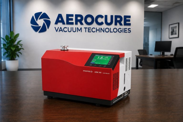
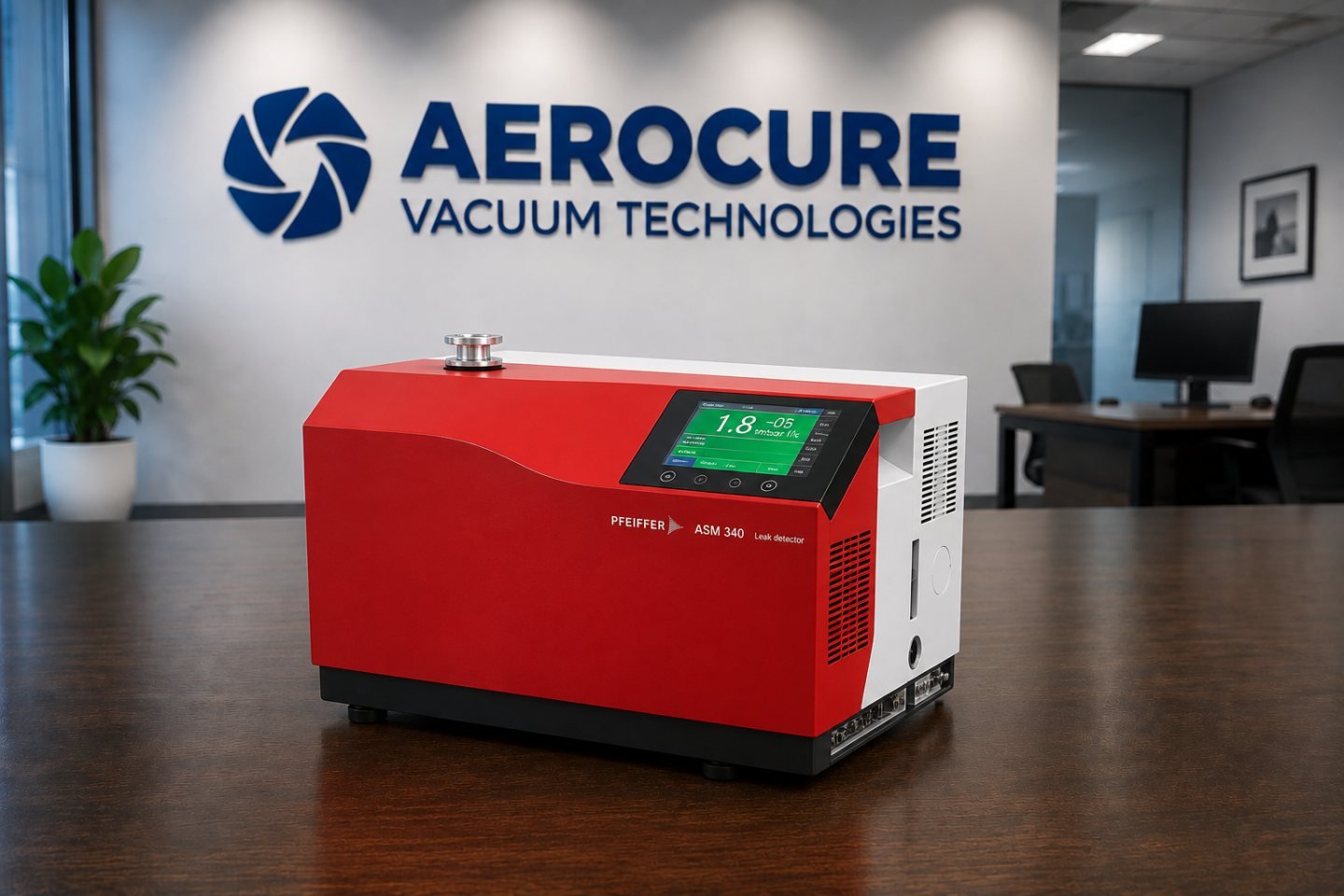
Use the leak detector only within its operating instructions. Confirm warm-up or stabilisation, inlet condition, test mode, units, calibration or reference-leak check, background and any external pump or partial-flow arrangement needed for the object.
07 — SAFETY & RECORD
Plan Gas Safety and the Test Record
Helium is inert, but released gas can displace oxygen, particularly in confined or poorly ventilated spaces. Cylinders and pressure systems add stored-energy and handling hazards. Complete the site risk assessment, ventilation, cylinder restraint, pressure regulation and emergency controls with competent personnel.
Record the test object identification, drawing or revision, method, boundary, fixtures, tracer gas, pressures, instrument and calibrated leak identification, calibration or check status, background, test points, results, acceptance basis, deviations, date and operator as required by the approved procedure.
PRACTICAL WORKSHEET
Pre-Test Information Checklist
Use this checklist to make a helium leak-testing enquiry technically reviewable. It does not replace an approved test procedure or safety assessment.
Objective & criterion
- Locate, quantify, verify or troubleshoot
- Leak criterion with units and reference basis
- Applicable drawing, specification or procedure
Test object
- Identification, revision, materials and volume
- Joints, seals, welds and suspected areas
- Photographs, drawings and accessible surfaces
Pressure & method
- Normal pressure direction
- Safe vacuum and overpressure limits
- Available evacuation, fill and detector ports
Condition & fixtures
- Cleanliness, moisture and prior process exposure
- Blanking, adapters, enclosure and supports
- Blind volumes, elastomers and trapped-gas risks
Environment & equipment
- Background helium and ventilation
- Detector mode, units and readiness checks
- Auxiliary pump, response-time or probe needs
Safety & reporting
- Gas, cylinder and pressure risk assessment
- Personnel and site-control requirements
- Required report, records and acceptance authority
PRIMARY REFERENCES
Technical Sources and Further Reading
These references support the general technical explanation. Always use the current instructions and approved procedure for the exact equipment and task.